How To Design a Cross Girder or Floor Beams in Bridges or Railway Bridge.
Cross girder
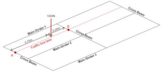
are provided in each panel, joining the corresponding lower panel points of two
truss girder.

The design procedure
is given by:-
Step 1:-
Loads:-
Effective
span of cross girder = 4 m (say)
The dead
load as transformed as the point load at 1 m from the ends of cross girder.
Self weight
of cross-girder = 3 kN/m (Assumed), it acts as uniformly
distributed.
The cross
girder is subjected to maximum live load when both the adjacent spans loaded.
EUDLL
(Effective uniformly Distributed Live Load) for 8 m span = 1056 KN (Say)
Impact
factor = 0.909 (say)
[Note: - Impact factor is calculated by
using this formula = 0.15 + [8 / (6+L)]
So, Impact
load is given by,
= 0.909 × 1056
= 960 KN
Live Load + Impact Load
= 2016 KN
 Half of live load and
impact load is carried by girder as two point’s loads at 1 m from each end.
Half of live load and
impact load is carried by girder as two point’s loads at 1 m from each end.
Point load due to
superimposed dead load {(1/2) × dead load per track for two stringer as calculated
in design of stringer}.
Point load due to live
load & impact load = [(1/2) × {1/2) × 2016}]
Total point load = sum
of two calculated load above in KN
Draw the loading
diagram with UDL and point load at 1 m from the edges.
The reactions at the
ends = Total point load + UDL span × span length KN
Step 2:-
Bending Moment at
centre:-
M = [(Reaction at each
end span / 2) – Point Load × 1 – (UDL load × span) / 2]
Allowable stress in
bending = 165 N/mm2.
Step 3:-
Section Modulus:-
Z = M / Sigmacbc ,
Where Sigmacbc = 165 N/mm2
From the Steel Table
Select ISWB section having greater than the value of Z as we calculated.
Step 4:-
Shear stress:-
Vn = Shear
force at the end / height of section selected above/ thickness of web tw and it should be less than
100 N/mm2. Otherwise
revise the section. Hence, safe.
Provide the details of
the section provided.


Comments
Post a Comment